Disclaimer: I don’t have a degree in electronic engineering. My knowledge comes from reading and experimenting. You should do your own research before trying to replicate my work.
The problem
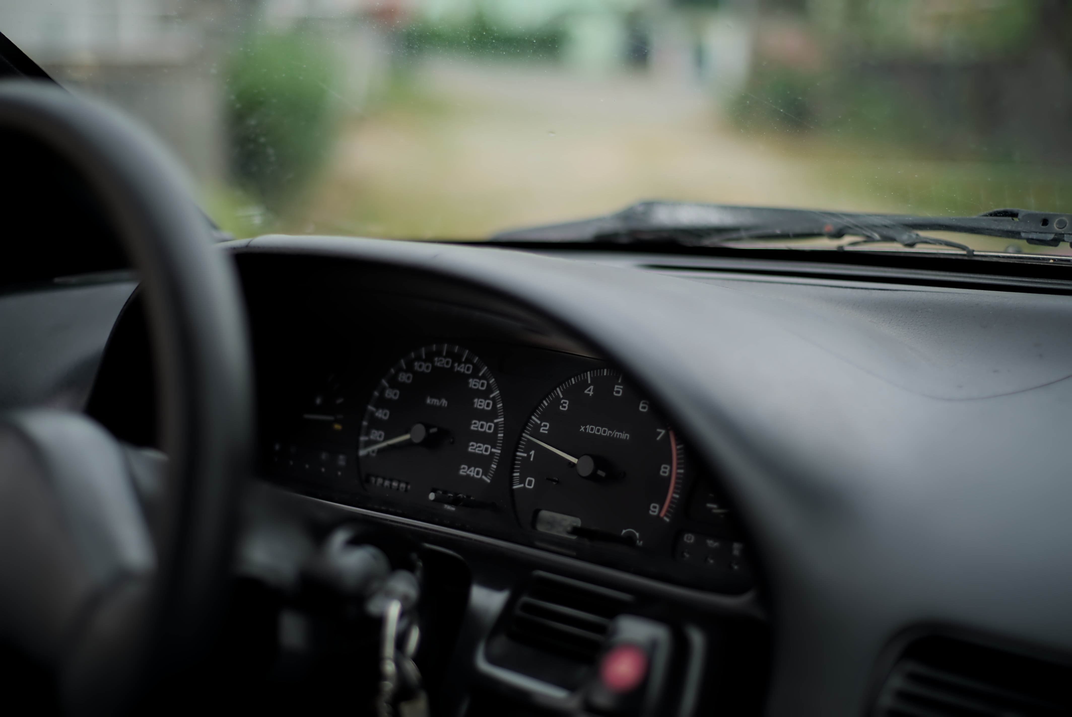
Old vehicles start to have issues as they age, and a common one with Nissan 200SX (S13) (240SX in America and 180SX in Japan) is the cluster that stops working, either the speedometer (more common) or the tachometer (engine RPM).
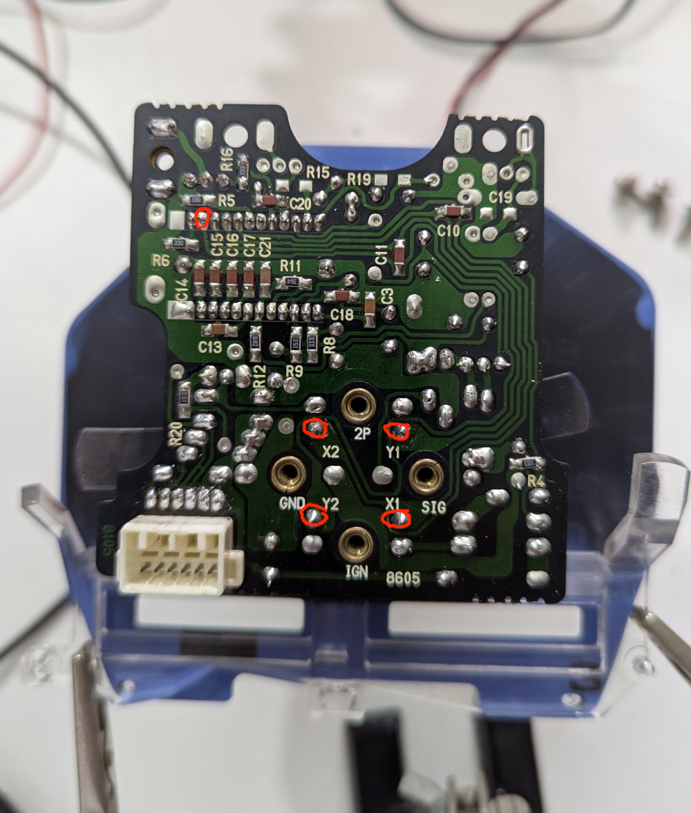
The issue with the speedometer is the needle that either stops working or jumps to the other end of the scale (240+ km/h). This is associated with broken solder joints (mainly X1, X2, Y1, Y2) in the speedometer PCB, and usually a reflow (resoldering) is enough to fix.
I had asked a friend to do this for me, and it fixed the needle moving over 240 km/h issue, but created a new one, where the needle didn’t move after reaching 82 km/h. Why 82 km/h? This took me a long time to understand. Inside the round metal shell, there are 2 coils wrapped in a cross (X) shape. This cross is tilted 45 degrees angle, and the upper limit on this 45 degree angle is 82 km/h.
So only one axis was being driven, and the other (from 82 to 270+ km/h) wasn’t able to move the needle. A person even reported only starting to work after 80 km/h, but being erratic after that. That would match the case of only the other axis driving the needle.
Since then, I’ve improved my soldering skills, so I decided to attempt to fix it by myself, but before doing it, I wanted to come up with a test on the lab to check if it was working properly, before installing it in the car and driving at more than 82 km/h to see if the issue was fixed.
Since I also had an issue with the tachometer, I also want to simulate this one in the lab to understand what the issue could be.
Tachometer Simulation
The first one I’ve tried to simulate was the tachometer. This uses a DC pulse signal from the CAS (Crank Angle Sensor) that happens 2 times per revolution.
rotations per minute = pulse frequency / 2 * 60 seconds
The easy way to do this would be buying a frequency generator, like this. But I didn’t have one, and I also wanted to know how I could change the needle position on a real car gauge, so this was the perfect time to learn how to do it.
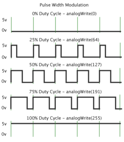
To simulate this with ESP32 (and with Arduino IDE) I need to send a 12-volt PWM signal at 50% duty cycle. If you don’t know about duty cycle (I didn’t), it is the amount of time the signal is high. In this case, 50% of the time the signal is high and 50% is low.
The first thing is to choose a PWM pin. The ESP32 has several PWM pins, so I used the GPIO 4 (D4).
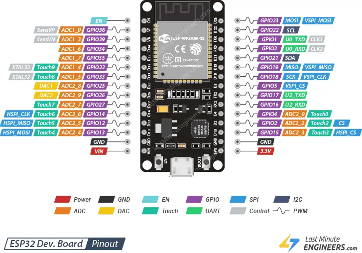
The second thing is to transform the 3.3 volts PWM signal to 12 volts. For this I’ve used both BJT transistor and a MOSFET, but for this use case a BJT is enough, since it doesn’t have too much current (under the 600 mA mention in the 2N2222 datasheet).
Although the IRLZ44N works with 3.3v from the ESP32, it will not be fully open, and MOSFETs aren’t meant to be in a transition state, becoming inefficient and generating more heat.
I decided to use 2N2222 for the BJT transistor (2N3904 would have probably been enough max current to be used as well) to drive the IRFZ44N.
The tachometer has 3 pins:
IGN(ignition, V12+),GND(ground)SIG(signal).
I was having some issues understanding how I could send the signal to the tachometer, but this example helped me out.
Here is the schematics:
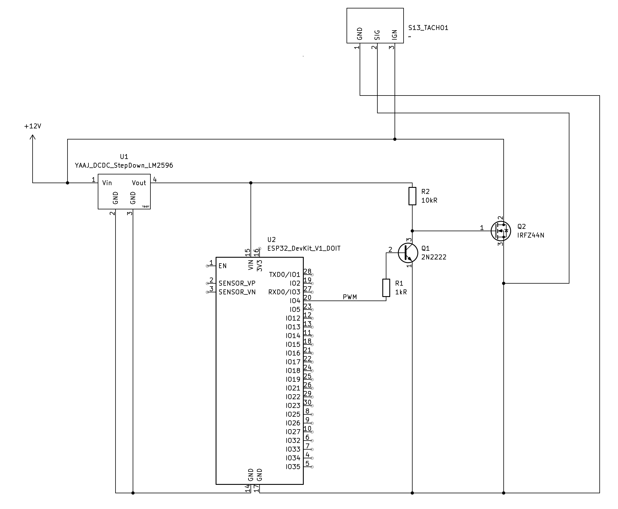
Components:
- Step-down LM2596 board
- ESP32 WROOM Devkit
- 2N2222
- IRFZ44N
- 1kΩ resistor
- 10kΩ resistor
- Breadboard and jumper wires (optional, but useful)
The code sets 3 RPM values (3000, 6000 and 9000) spaced by 1 second from each other.
// Define the pin you want to use for PWM
int pwmPin = 4; // Example: Using GPIO 4
int ledPin = 2;

// Define the PWM channel and frequency
int channel = 0;
int baseFrequency = 100; // 100 Hz
int resolution = 8; // bit resolution

void setup()
{
    pinMode(ledPin, OUTPUT);
    digitalWrite(ledPin, HIGH);

    // Attach the pin to the channel and set frequency
    ledcAttach(pwmPin, baseFrequency, resolution);
}

void loop()
{
    digitalWrite(ledPin, HIGH);
    // 3000 rpm
    ledcWriteTone(pwmPin, 100);
    delay(1000);
    // 6000 rpm
    ledcWriteTone(pwmPin, 200);
    delay(1000);
    // 9000 rpm
    ledcWriteTone(pwmPin, 300);
    digitalWrite(ledPin, LOW);
    delay(1000);
}
In this example, I also control the LED pin to know when the ESP32 is running the code. I had some issues with the breadboard I was using, causing the ESP32 to reboot frequently, not being able to understand why I didn’t get the PWM values when running via 12 volts, but working properly when using USB.
Everything worked as expected, but I couldn’t replicate the same behaviour in another RPM gauge from a Renault 19. I believe that in some cars, they expect a higher signal from the distributor.
Speedometer Simulation
The speedometer works in a different way than the tachometer. In this vehicle, it uses a 2–wire reluctor speed sensor to provide speed information. This sensor generates an AC signal to the cluster that translates into a Hall effect signal to the ECU.
The AC signal changes in amplitude and frequency as the speed increases.
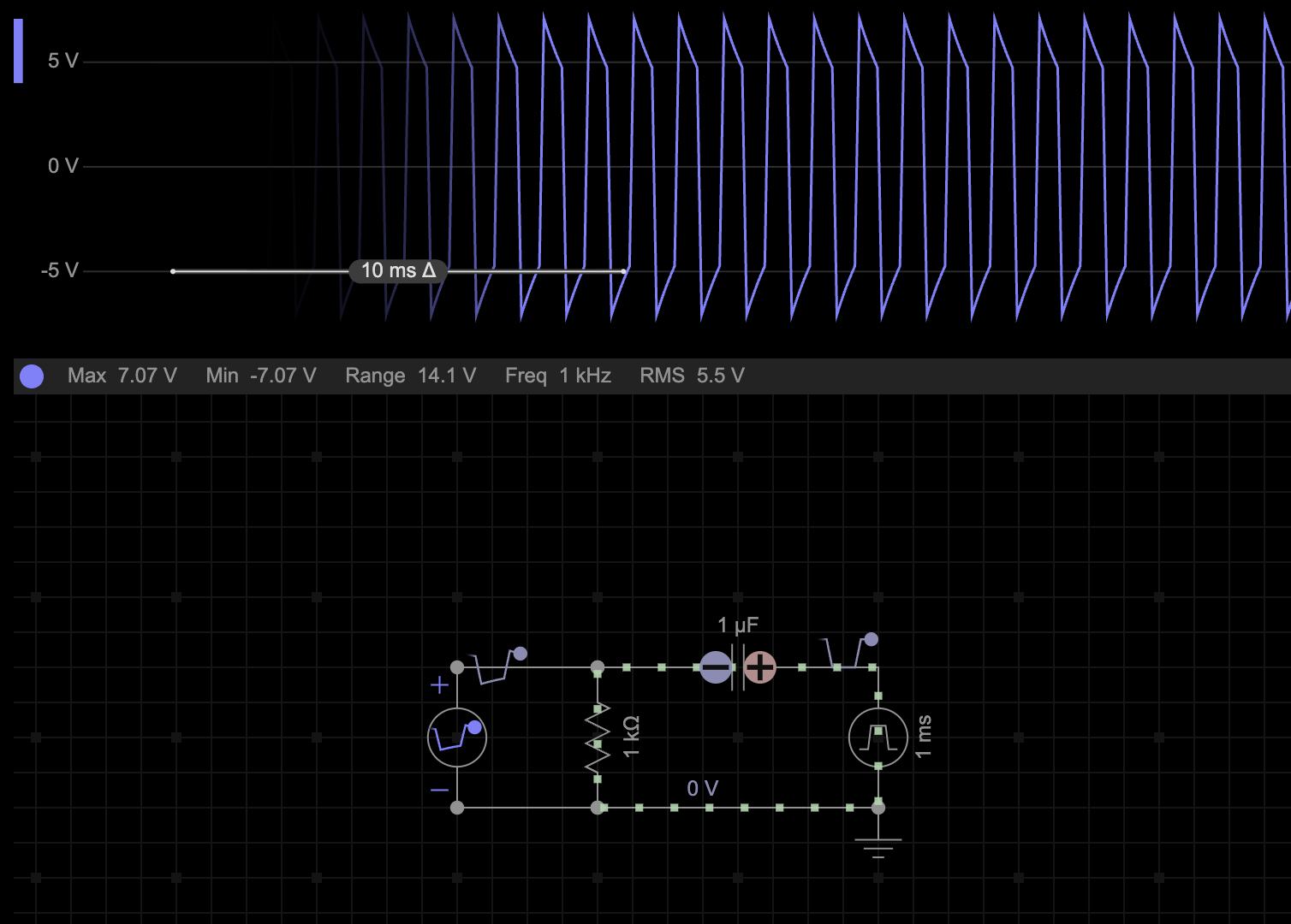
To simulate an AC signal with DC, I started to investigate what the options were, but the simplest would be to use a capacitor and a resistor in series to shift the DC square wave signal from the PWM (generated between 0 and 12 volts) to an AC square wave signal (between -6 and 6 volts).
I used the previous schematic and the base for this one, and added the new components. The new AC signal was 4.7 volts, and I’ve used the previous frequency but added a new step by setting the frequency to 400 Hz. After uploading the code, the needle was moving between 0, 30, and 60 km/h, but didn’t reach the 90 km/h, which was the value I wanted, to replicate the “bug” of not going past 82 km/h.
The issue was regarding the voltage not being high enough for the frequency I was using, so I modified the resistor value before the conversion to the AC signal to allow more current to flow. Modifying the 10k ohms to 4.7k ohms was enough, and now the signal was 5.6 volts, enough to reach over 82 km/h.
Fixing speedometer
I’ve tried to resolder X1, X2, Y1, and Y2, but it took me a while to fix it. Not sure if the reason was that, or this time I also soldered the IC1 pin (top row, 2 on the left side) that is connected to Y2, which was lacking some solder.
Video with the speedometer fixed.
But between attempts, I took some time to reverse engineer the device and create the schematics for the speedometer. It was my first time doing schematics and using KiCad, so there were some issues moving things around, and I might have misunderstood some traces. It is also missing some resistor values, for which I didn’t take the time to read the band colors.
Feel free to submit updates about the schematics in the GitHub repo.
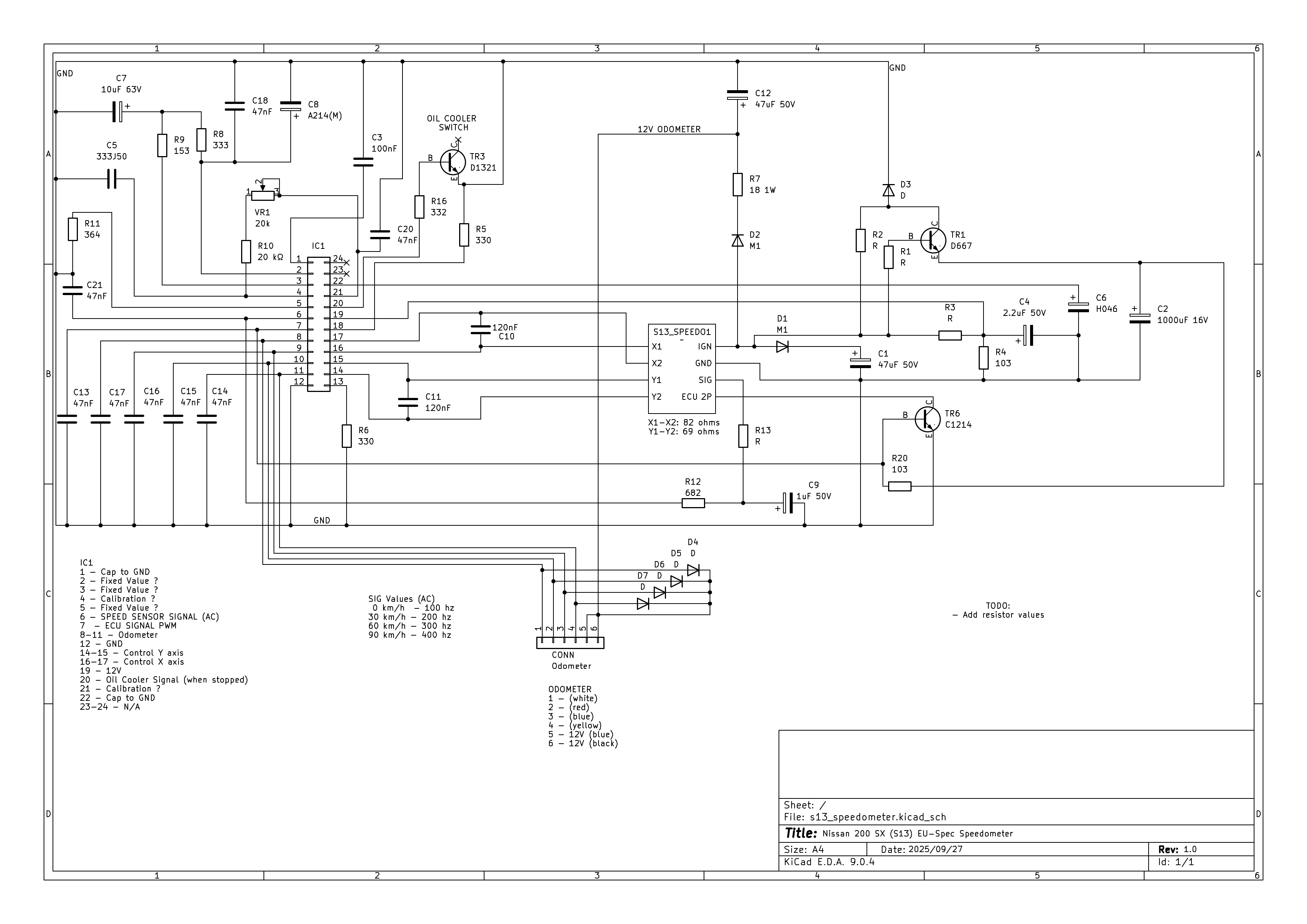
For the small capacitor values, I used the ones provided by Shaker783396.
Conclusion
It took me 2 weeks to finally fix it, but this was a fun project to take on. All the hours looking into Rossmann repairing Apple Macbooks motherboards made useful now.
One cool thing would be to replace this module in the cluster with a custom one that uses more modern electronic and stepper motors instead of coils. There is a guy doing that for the Mazda RX7 (FD). This forum also has a good thread of common issues with these clusters.